David Cook of the Robot Room asked us if we'd carry the partner PCB's for his book 'Robot Building for Beginners'. As we're an enthusiastic fan of this excellent book, we agreed to carry it for him. (even though we don't sell the book...yet!) Please note: You require a copy of this book to successfully […]
Starry Night Pendant Assembly Guide
We've already blogged about the Technology Grad Dresses, which are accompanied by the Starry Night Pendant as a perfect finishing touch to complete the outfit. Since then, we've upgraded and improved the Pendant design to make it a fully documented kit, rather than just a bundle:
- The 2xAAA battery holder offers longer life, less cost and avoids the need of a special charger that the LiPoly cell requires.
- We added a 16-LED ring option in addition to the standard 12-LED ring for more versatility.
- Assembly alignment pegs to ensure the perfect fit.
Parts:
1 x Pro Mini 3V micro-controller
1 x Adafruit NeoPixel Ring
1 x 2xAAA Battery Holder with Cover and Switch
2M x Superflex Wire
4cm x 3/4 HS-BK - 3/4 inch Heat Shrink
2.5cm of 1mm Heat Shrink
1 x DSST - Double Sided Sticky Tape
1 x Acrylic parts panel
1 x Special Glitter Acrylic front
Tools:
- Soldering Iron & solder
- Wire cutters
- Super Glue (a.k.a.: Cyanoacrylate Glue)
- Lighter or heat gun
Initial Acrylic Assembly:
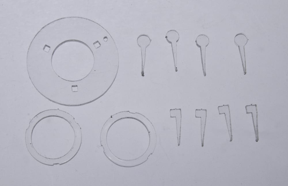
We'll be using these little pieces to align up the parts of your pendant for accurate gluing.
1. Remove brown paper from all parts and guides.

2. Insert a round peg into an alignment hole on the large clear part.
3. Gently wedge a square peg into the same hole from the other side, locking the two pieces together. We match the round and square pegs so they align the disks better than just randomly plugging two wedges together. It has to do with the way the wedge faces seat against each other.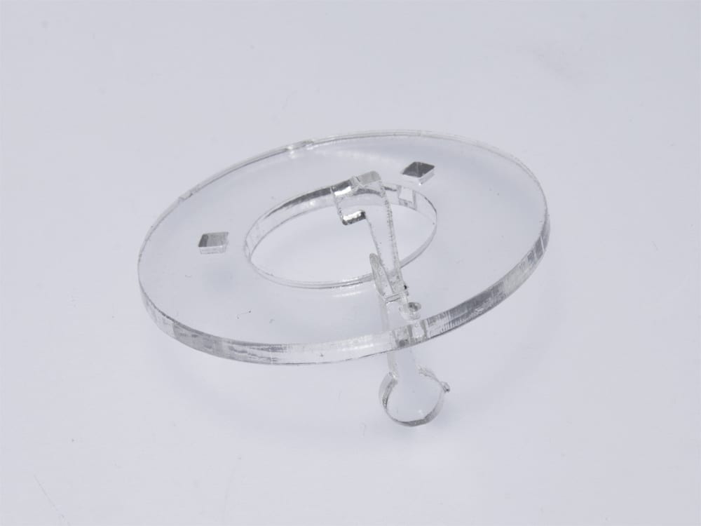 4. Repeat steps 2&3, on another hole, matching the orientations (squares-up; circles-down)
5. Place the thin plastic spacer rings against the first 2 sets of pegs, and lock the rings into place again with a repeat of steps 2&3 on the last hole.
6. Your 3-ring assembly should look like this before gluing: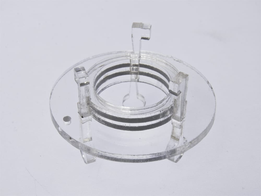
7. Use a drop of super glue to secure the thin spacers to each other, and to the clear back. AVOID gluing the alignment pegs, which are only temporary!
8. Once all glued, remove all pegs. If you did glue them, you can snap them clean off and file down the bumps. Really, it's best not to glue them in.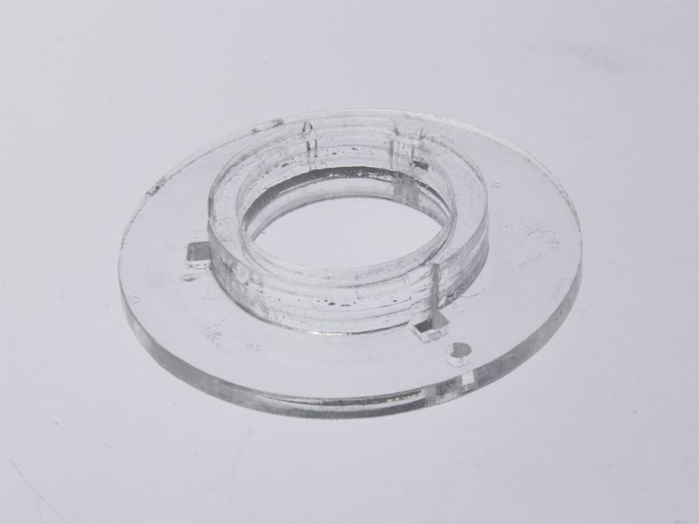
LED Ring Wire Preparation
The Superflex wire is really something special. It has a nylon core, wrapped with 7 enamel-coated wires that make it quite handy for wearables. But you can't use them quite like normal wires, so read this section before doing it.
1. Fold the Superflex wire in half, then in half again, to make 4 equal lengths. DO NOT CUT!
2. Melt a 3~4mm ball (1/8") of solder to the tip of your soldering iron. You usually don't solder this way, but this is a special case. Place the soldering tip with its molten drop of solder into the bend of the wire. We are melting both the nylon core and the enamel wire coating so we can make a nice pre-tinned section of wire.
The process takes approximately 5~10 seconds, and the wire section will smoke a bit, which is expected. You will end up with a slightly charred, but solder-tinned section of wire.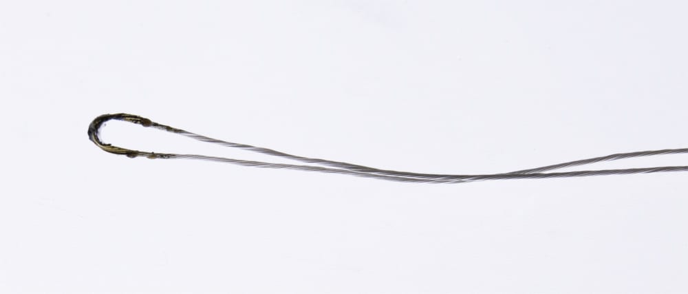
3. Snip this now-tinned bend in half, resulting in 2 ends being tinned.
4. Prepare the last 2 ends using the same method. You now have 4 equal lengths of Superflex wire ready.
LED Ring Electronics Assembly
5. Take TWO of those wires and solder them to the GND pad on the LED ring. Yes, two wires.
7. Solder ONE wire to the 5VDC pin on the ring
8. Solder the last wire to the Data In pin on the ring.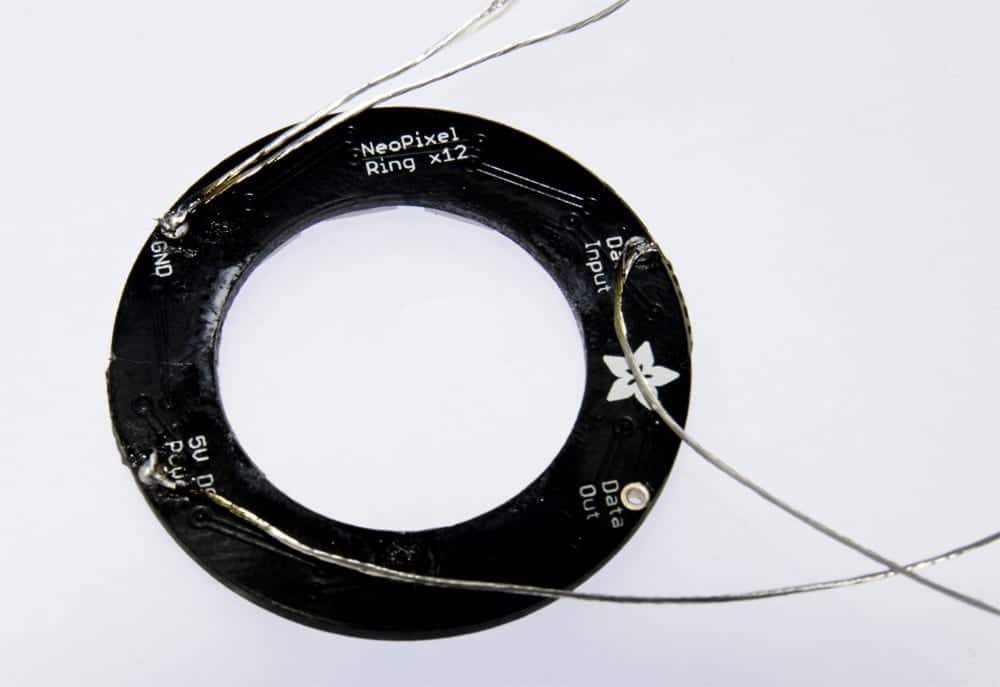
9. Feed all wires through the hole in the acrylic assembly, and snug the LED ring into place on the assembly. Now is a good time to use a marker to mark the 2 GND wires and the 5V wire. I often use one stripe on a wire to represent "-", and two stripes to identify power (because "+" is made up of 2 lines).
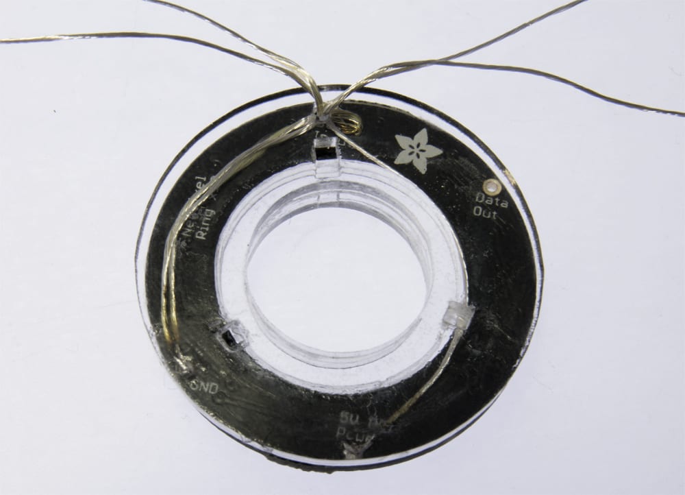
10. Pass all the wires through the small piece of heat shrink tube, and gently heat the tube until it snugs down around the wires. Not too much heat as you can burn the Superflex wire insulation easier than regular wire.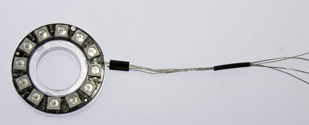
Battery Box / Processor Assembly:
To make this assembly compact and wearable, we're going to modify the battery box for a cleaner installation.
1. Open the battery box, and push/pull the red & black wires back out of their end exit hole. Use pliers to gently remove the spring contact connected to the black wire by pulling the spring mount straight up and out.
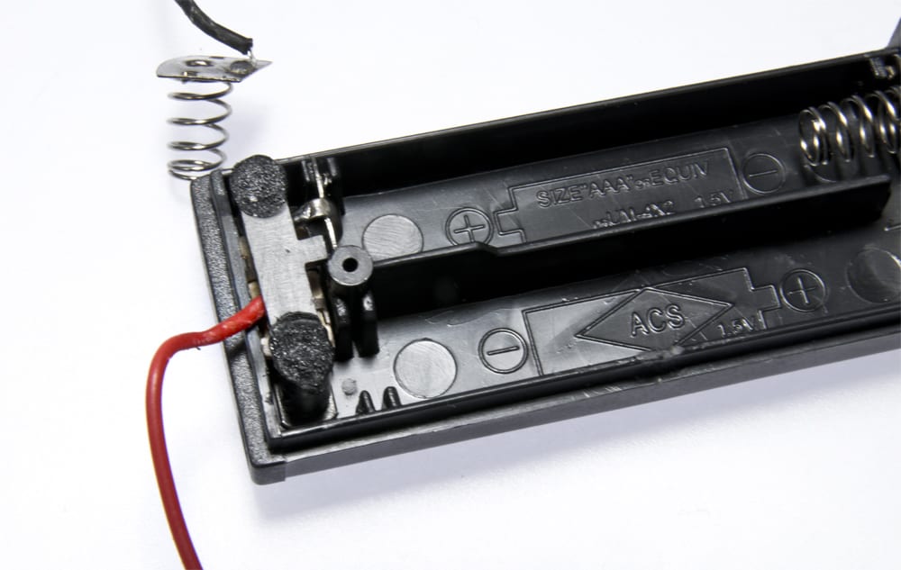
2. You will see we've prepared a small hole through the back of the box to accommodate the new, cleaner wiring.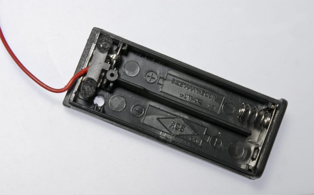 3. Run the red and black wires through the new exit hole on the side.
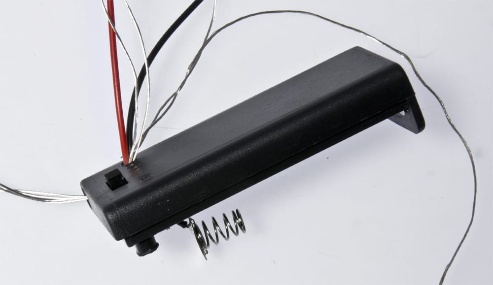
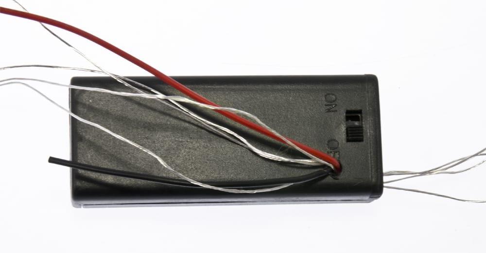
4. Run the 4 SuperFlex wires attached to the LED ring IN through the OLD hole, into the battery box, and OUT the new hole so the loose ends are out the new hole.
5. Solder the black battery wire, and the 2 GND Superflex wires to the Arduino Pro-Mini pin labeled GND. (Glad you marked those Superflex wires now, right?)
6. Solder the red battery wire, and the 5VDC Superflex wire to the Arduino Pro-Mini pin labeled VCC.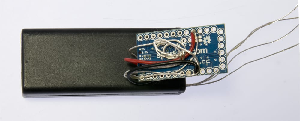
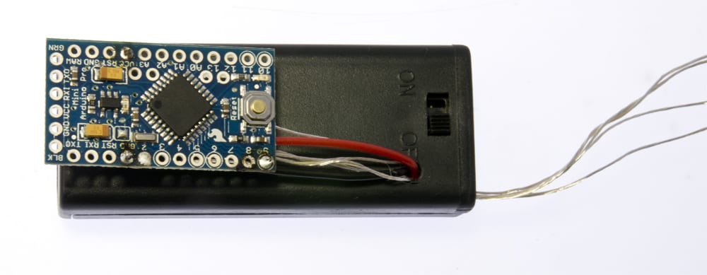 7. Solder the "Data In" Superflex wire to the Arduino Pro-Mini pin labeled 9.
8. Insert your batteries into the pack, and switch it on, being ready to turn it off quickly if nothing happens in the first 5 seconds. A misconnected power wire can cause damage, so always be ready on the first power-up!
9. Did a LED light up on the Pro-Mini? Did your LED ring come to life? Excellent - carry on! Otherwise, turn off your battery pack and remove the batteries, and re-trace your wires. Make sure all solder connections are clean, and not accidentally bridging over to any other connections.
9. If all is working well, slide the large heat-shrink tube over your Pro-Mini, and gently heat it until it snugs down to a tidy package.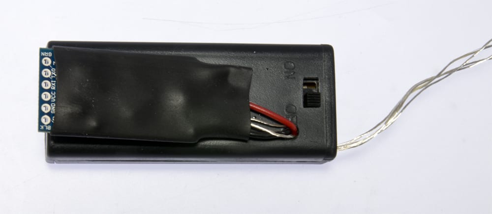 9. Use the double sided sticky tape to glue the Pro-Mini to the battery box.
Final Assembly:
1. Carefully snug down the wiring to the LED ring/acrylic assembly.
2. Apply a drop of glue to the center acrylic.
3. Line up the sparkly acrylic front, and hold until the glue sets.
WARNING: If you decide to re-program the Pro-Mini, ALWAYS remove batteries before programming. You do not need conflicting power sources potentially damaging each other. We have seen batteries hiss and pop!
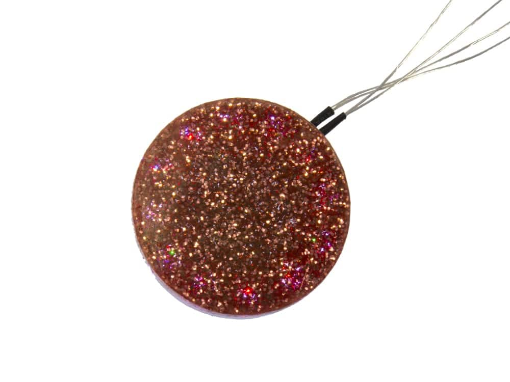
Wear the Pendant around your neck, with the battery pack nestled either hanging long into the small of your back, or short tucked up under your hair. They are similar in weight so you should not find it creeping substantially either way.
Depending on the situation, you may find facing the pendant's LEDs towards your skin is more suitable, subtle effect. For out-and-out BLING, wear it with LEDs outwards!
The standard flicker program with fresh alkaline batteries will last well over 10 hours. The more dazzle you add, the less life the piece will have. Fortunately, it still looks splendid when out of power.
MORE POSTS
Wednesday, the boring ol' hump of the week. What better way to pull through than with some distractions? Here's our latest batch of neat-o internet distract-o thingers: Sylvan Lake Robotics Club Looking for Members If you're around the Sylvan Lake area and what to dip your toes into the big ol' pond that is robotics, […]
Now that the season of mass gift giving is (temporarily) over, publishing the details on this special gift ocarina box for a wedding anniversary will not ruin a surprise. So I figured I'd share this personal project that uses simple but smart electronics. First I soldered an interrupter switch to the SuperFlex LED Strand with Battery Pack in color purple. […]
It is my unfortunate duty to inform the customers of Solarbotics who have used our web interface to place credit card orders that this information used on solarbotics.com has been compromised.
Solarbotics, Ltd. is not responsible for misprints or errors on product prices or information. For more information, please see our Terms and Conditions.
Warning: This product contains chemicals known to the State of California to cause cancer and birth defects or other reproductive harm.
Please visit www.P65Warnings.ca.gov for more information. This item was manufactured prior to August 31, 2018.

