Psst. Hey. You. I have a secret. A secret we want everyone to know about. But only the people going to the San Fransisco Maker Faire. The word 'free' is a pretty good word, right? Let's throw 'Arduino' in there too. We may be onto something here... How about 'workshop', just for good measure? Those […]
Project Monday: Laser Monitoring with Sy...
 I'm Dilan, a relatively new hire here at Solarbotics, and I am in charge of product development and R&D support. I've got tons of experience with many things, and have seen Arduino as a staple in many projects here at Solarbotics. With its ease of use, powerful programming language, and vast online community, it has been the go-to platform whenever a quick solution is needed. But when I needed some wireless communication, I'd choose a system like Xbee/Zigbee or even simple 433MHz modules, where the communication interface was still treated as a dumb serial link between the two systems. With Solarbotics' use of Synapse, I needed to project to get to know a more advanced wireless system.
Solarbotics has been playing with Synapse SNAP modules, and have featured these modules in various projects in the past, like our our wireless Brutusbot and with a tutorial on how to get started with Synapse. This system has potential, and it was time to bend it to my will!
Why Synapse?
Some quick details about Synapse, and why to consider them for your project:
- Instant mesh-networking. Unlike similar XBee/Zigbee devices, these simply talk to each other. And if you need more range, just plop another unit in between. Done!
- Fast and powerful. Even the cheapest unit can do 450M (1500'), up to 2Mbps. Let's see a cheap 433MHz unit do that!
- Built-in microcontroller. Although it's Arduino-friendly, there's no need for it for simpler applications. 7 A/D ports, 6 PWM outputs, and 9 interrupt-capable pins, plus I2C and 2 Uarts on the least expensive RF200P81 model. That's lots to work with.
- Cost. The least expensive model is only $19.95. They're all compatible; it's just what feature set and range what determines what model you want.
Development
After breadboarding up one of the RF100 SNAP modules with the use of our breakout board, I started in on the above tutorial and instantly fell in love with the amount of functionality that these modules provide. While there is a small hurdle of learning the syntax of Python, any experienced Arduino user can be fully up to speed in a few days hacking with SnapPy (Synapse' version of Python).
The amazing part about these modules is their ability to mesh network by default. You can use a single SNAP module to communicate with a huge number other modules by just specifying the target's address. Being mesh-networked means talking with a remote module is straightforward as long as long as you have other modules in-between.
However I'm going to try to stay out of the details of my intimate love affair with Synapse just in case my wife is reading this article. What I want to focus on today is the practical application of how I used these modules to solve a long standing problem here at Solarbotics.
We produce a lot of acrylic parts. Sales of Useless Boxes often means our team of lasers is running non-stop. A production problem we often hit is notification of a laser's "Job Complete" signal, which is a soft "beep", and is often missed in the loud lasering room. Although the lasers are continually monitored, they can easily sit overlooked for 20-30 minutes while waiting for an unload by the production team. By the end of the week these delays add up and that's something we don't want.
This is where the use of Synapse comes in. We want to have a SNAP module monitor each laser's "job complete" beep signal, and send the status via the mesh network to the Master node that will pester the production team with a "HEY! Change me!" signal. Less time wasted, less power used, and a more efficient production team!
Sensing Laser Beams
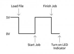
I started by fleshing out how to interface a Synapse module to our biggest laser, aptly named "Papa" (the most powerful and somewhat… the least smart one of the three in the laser family here at Solarbotics). I was happy to see that in a previous project we had already brought out the "Laser Firing" signal to our custom air assist circuit, which turns off the compressed air line when the laser is not cutting. A high (5V) signal indicates laser is cutting and low (0V) when the job is finished (image below). On turn-on, the "Laser Firing" signal goes high until the file is loaded, then acts as a traditional "5V for on", "0V for off" signal. Yay for traditional 5V logic!
But as SNAP modules are 3.3V logic, I a simple voltage divider to bring the signal down to safe levels. With this signal, I'm able to detect job completion, and trigger the LED indicator of the Master module.
Finished Module:
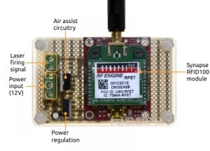
As we were stealing the signal for the air assist valve, we merged the control circuitry with our laser monitor board. We used BPS protoboards and a prototype "Circuit Sammich" protective acrylic to mount the screw-down connectors, voltage regulation, air-assist relay and Synapse module. We're using the SMA antenna version of the RF100 module so we can optionally move the antenna off the laser for best signal quality.
Since SNAP modules can be programmed with Python, I was able to completely drop the use of an Arduino. This decreased the overall size of the device while increasing the wireless functionality - a win/win in my books. No need to code twice - the event-driven embedded python in the SNAP module was more than adequate for this application.
The Code
Python is great, but due to hardware restrictions, there are some limitations to note when working with the Synapse' SNAPpy python:
- No For/Next loops are not supported. This was a bit aggravating. You can use do/while instead but it can be cumbersome and ugly. I'm not sure why it's not supported, but alas, that is how it is. This quirk is also followed by
- No float, long, lists (arrays), and classes. These are all annoyances to the way most of us are used to coding, but the usefulness Synapse provides is compensates for these shortcomings.
Synapse uses the event driven programming model. Instead of running a continuous loop like Arduino, Synapse will only execute code when an interrupt is triggered. This interrupt can be one of many things, but for this code I only utilize interrupts from input pins as well as a timer that triggers an interrupt every second.
While I'm not going to go into a huge amount of detail about the code (I've made sure to include extensive commenting), I feeling like a brief description of how it functions is required.
@setHook(HOOK_GPIN)

def togglePin(pinNum, isSet):  #Passes the pin number that toggled Interrupt and if a high or low signal

global lStatus, lFlag  #Use global variables instead of making locals

if isSet == True:  #If the signal is high (3.3V)

if pinNum == lStatus:  #If the pin was the lStatus pin
lFlag = False	 #Set the flag to false

elif isSet == False:  #If the signal is low (0V)
if pinNum == lStatus:  #If the pin was the lStatus pin
lFlag = True  #Set the flag to true
The main function of this device is to monitor the laser firing signal to sense when it has finished a job. To do this we use the @setHook(HOOK_GPIN) interrupt. This will sense when any monitored pin which transitions between high (above 2.31V) or low(below 1.16V). It will then execute the togglePin(pinNum, isSet) function that will set a flag to indicate if the laser has finished cutting or not.
@setHook(HOOK_1S)

def updateFSM(tick):

global lCount, lTimeout, lFlag, dFlag

if lCount < 10 and lFlag == True:  #If the laser has finished and it has been less than 10	#seconds.

lCount += 1  #Increment the counter by 1
print(lCount);

elif lCount >= 10 and dFlag == False:  #If it has been 10 seconds or greater, and the done flag                                                                                #hasn't been set.

rpc(masterAddress, 'laserFinish', "papa")  #Tell the master node that the job has been completed.

print("RPC Called");
dFlag = True  #Set the done Flag to True so that the master
		#node isn't poled again.

elif lFlag == False:  #If laser has not finished a job or else not started a job
lCount = 0  #Reset the counter
lFlag = False  #Set the flag to false
dFlag = False
If it has sensed a high signal, it will set a flag to say that the laser has finished. After 10 seconds of the done flag being set high, the module will execute the function rpc(masterAddress, 'laserFinish', "papa"). This is where Synapse really starts to shine. The function rpc() will allow you to execute a function on another module. You can specify the address, function, and parameters you will pass. In this case, we are specifying an address of masterAddress, and will execute the function laserFinish which takes the argument of "papa". This will in turn tell the Master module that the papa laser has finished a job and that it should turn on the indicator LED.
Flashing LEDs
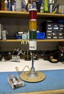
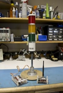
Now that the laser monitoring device had been completed, the next step is to build the LED indicator. Below is an image of the three lights that represent the three different lasers we have in the warehouse. It originally contained 3 incandescent bulbs that ran at 12V which I didn't like. So instead, I ripped them out and replaced them each with a high power 2.8 watt white LED (Ooooo shiny!). This allowed me to use one of our Star Controllers to control each LED with the default 3.3V of the Synapse module.
The control box features a Synapse RF100 module with the integrated chip antenna. Another SMA model would have been preferred, but the larger antenna would have been in the way (and this is all we had in R&D at the time!).
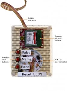
On the bottom we have the round Star Controller circuit board, which interfaces low voltage/low current microcontroller pins with high voltage/high current LEDs. Each channel of the Star Controller (usually used to control an RGB LED) drives 350mA into each white LED in the light tower, which we've found is quite adequate to illuminate the indicator nicely.
On the left are the three pushbuttons. We use these buttons to turn off the indicator once the laser has been restarted. The buttons are wired to pull the Synapse lines from 3.3V to 0V. A 10K ohm pullup is used to provide a known state. As before, the electronics have been soldered to another BPS protoboard and then enclosed within a prototype "Circuit Sammich".
The Code
The LED indicator station simply displays the completion status for each laser. When a laser has finished, its monitoring device will execute a function on the Master module (inside the LED indicator) which sets a flag stating that the indicator LED for that laser should be turned on.
def laserFinish(laserName):

global rFlag, gFlag, bFlag  #Use the global variables instead of making locals

if laserName == "baby":  #If the laser that called the function passed the string "baby"

rFlag = True  #Turn on the baby LED indicator by setting the flag to True

elif laserName == "mama":  #If the laser that called the function passed the string "mama"

gFlag = True  #Turn on the mama LED indicator by setting the flag to True

elif laserName == "papa":  #If the laser that called the function passed the string "papa"

bFlag = True  #Turn on the papa LED indicator by setting the flag to False
Above we have a code snippet of the function that handles setting the flag for each laser. When the laser monitor calls the function rpc(masterAddress, 'laserFinish', "papa" ), it will set laserName to "papa". Since this meets the condition of the second elif statement, bflag is set which will make the Synapse module blink the b-channel of the Star Controller which represents the "papa" laser LED.
@setHook(HOOK_GPIN)

def togglePin(pinNum, isSet):

global rFlag, gFlag, bFlag  #Use the global variables instead of making locals

if isSet == False:  #If the interrupt was triggered by a high signal
if pinNum == bInput:  #If the pin being triggered is the baby laser reset button
rFlag = False  #Turn off the baby LED by setting the flag to false

elif pinNum == mInput:  #If the pin being triggered is the mama laser reset button
gFlag = False  #Turn off the mama LED by setting the flag to false

elif pinNum == pInput:  #If the pin being triggered is the papa laser reset button
bFlag = False  #Turn off the papa LED by setting the flag to false
If a flag has been set by a laser and the LED is being flashed, it can only be turned off by pressing one of the reset buttons. When a button has been pressed, it will toggle the @setHook(HOOK_GPIN) interrupt which will then set a flag false depending on which button triggered it.
Note that HOOK_GPIN passes two variables to the function that is executed by the interrupt; pinNum (contains the pin number of which pin triggered the interrupt) and isSet (states whether the interrupt was a high or low signal). In the code above, we will only reset a flag if the interrupt was a low signal and the pin was one of which that were assigned to each laser.
@setHook(HOOK_1S)
def updateFSM(tick):

global rFlag, gFlag, bFlag  #Use the global variables instead of making locals

if rFlag == True:  #If the baby laser flag has been set to true

pulsePin(rPinLED, 500, True)  #Turn on the baby laser LED indicator for 0.5 seconds

if bFlag == True:  #If the mama laser flag has been set to true

pulsePin(gPinLED, 500, True)  #Turn on the mama laser LED indicator for 0.5 seconds

if gFlag == True:  #If the papa laser flag has been set to true

pulsePin(bPinLED, 500, True)  #Turn on the papa laser LED indicator for 0.5 seconds
Every second, the @setHook(HOOK_1S) is triggered and will execute the above function which will turn on the LEDs for the corresponding lasers. The function pulsePin() is extremely helpful since it will pulse a pin either high or low for a specified duration. In our case, I pulse the pin for each LED high for 500mS. Since the updateFSM() function runs every second, each LED is effectively on for 0.5 seconds and off for 0.5 seconds if it's flag is set to True.
Although not as cheap as "keyfob" type transceivers, these inexpensive Synapse units offer considerable utility, especially considering it has an inbuilt microcontroller available for your use. While there may be a bit of a learning curve for python, I can personally say that the investment in time was very well worth it.
MORE POSTS
Well, last week I told you that I'd have (and I quote) "something more exciting and substantial for you." So I'd like to take this opportunity (on behalf of the other fine folks at Solarbotics) to welcome the newest addition to the team, Tom! He'll be heading up purchasing and finding neat new toys to […]
As great Creality Printers generally are, it's still a hassle to get parts and pieces to fix or enhance your printer. This explains why we were quite thrilled to see some BIG boxes come in from Creality the other day, containing: Replacement Ender-3 24V Hot Ends CR Series Inductive Leveling Kits BL-Touch Kits Ender-3 1.1.5 […]
We needed all our superpowers for the Calgary Comic & Entertainment Expo this past weekend, so we decided to create our version of Arc Reactor for the team to wear at the show in order to augment the intelligence and add superhuman-level multitasking and learning capabilities (imagination is key at the Comic Expo).
Solarbotics, Ltd. is not responsible for misprints or errors on product prices or information. For more information, please see our Terms and Conditions.
Warning: This product contains chemicals known to the State of California to cause cancer and birth defects or other reproductive harm.
Please visit www.P65Warnings.ca.gov for more information. This item was manufactured prior to August 31, 2018.

