Assembly Guide
First, download the official manual/assembly instructions here:
Although the Creality Ender-3 Pro is pretty straight-forward, we've rounded out the assembly instructions. Start by reviewing their documentation, and use our following notes for additional help/clarity:
Recommended Optional Tools
- Square with a 100mm(4"~) or less side
Step 1
When assembling the uprights, you may find it useful to hang the machine over the edge of your work surface to support it while screwing them in. Use a square and check to ensure that they are at a right angle with the bottom frame. Don't completely tighten them yet, just make sure they are snug.
Step 2
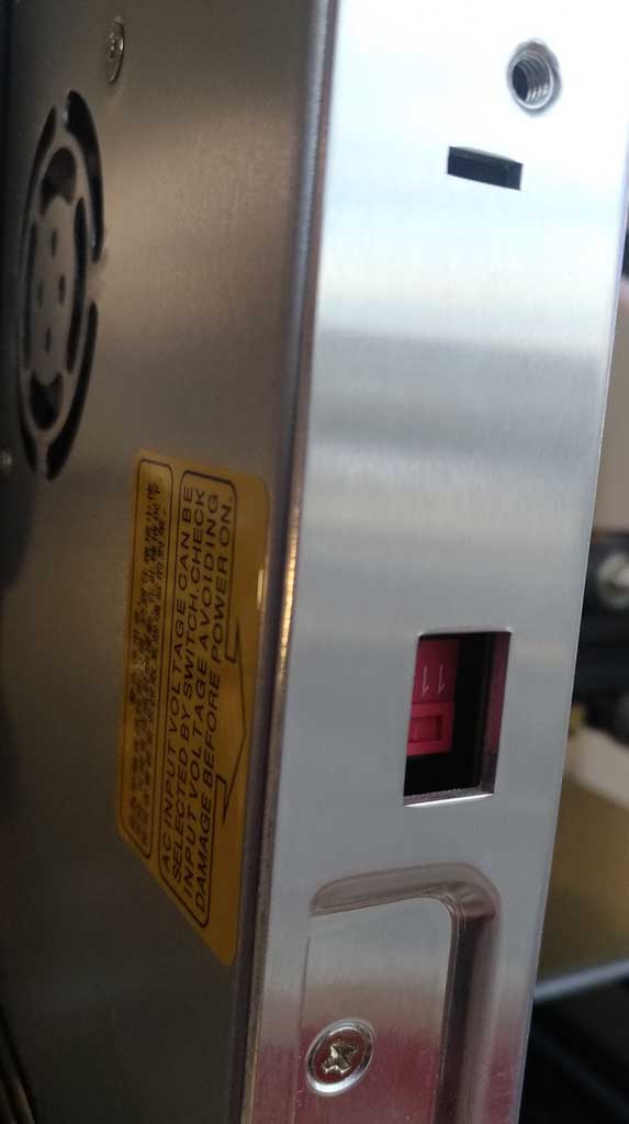
*** CRITICAL ***
Make sure that you set the voltage of the power supply to 115v. You will see a small opening with a red switch inside, ensure that it shows 115v.
YOU CAN SERIOUSLY DAMAGE THE PRINTER IF THIS IS NOT CHANGED BEFORE ATTEMPTING TO TURN ON THE MACHINE
Step 3
As the instructions mention, make sure that the nuts are turned to fit into the slot. When you tighten them in, ensure that they rotate 90° to grip the inside of the rail and lock them into place. If they don't, back out the screw a bit, and put a small amount of pressure on it while retightening to ensure the t-nut stays at the back of the slot for as long as possible so that it can rotate into place. Do not push so hard that it is unable to rotate.
Step 4
No Additional Notes For This Step.
Step 5
Before completely tightening the two M4x16 screws, push down on the extrusion between the screws. This helps to ensure that the x-axis is at a proper right angle to the wheels while tightening each screw. If you run your finger along the edge of the bracket parallel to the extrusion it should feel even the entire length.
Step 6
No Additional Notes For This Step.
Step 7
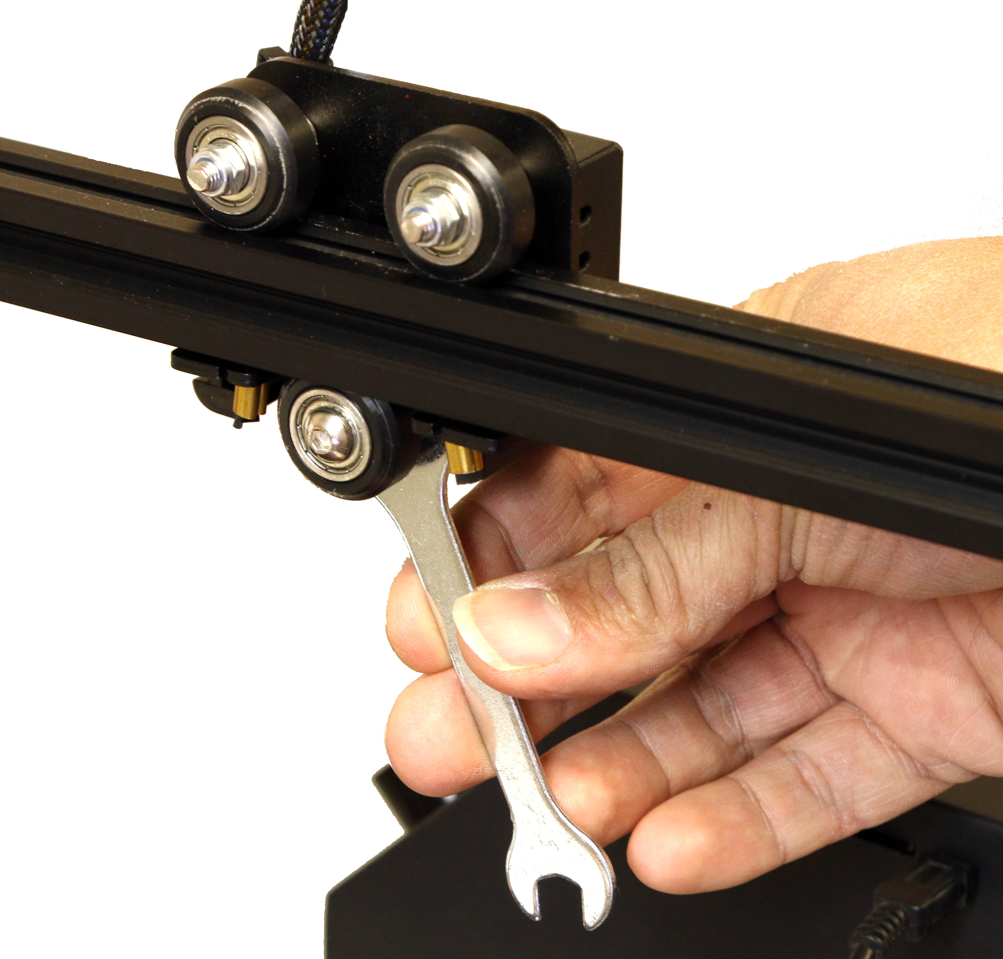
Slide the extruder assembly (05) onto the extrusion before you attach the wheel bracket, with the belt going underneath the two wheels, in the channel on the top. After you have done so, use the included wrench to tighten the eccentric nut attached to the bottom wheel until the whole assembly can slide freely but can't be tilted/wiggled on the extrusions. You'll know it's right if you're able to move the bracket by rolling a wheel with your finger, but the same wheel can still turn if you hold the bracket in place.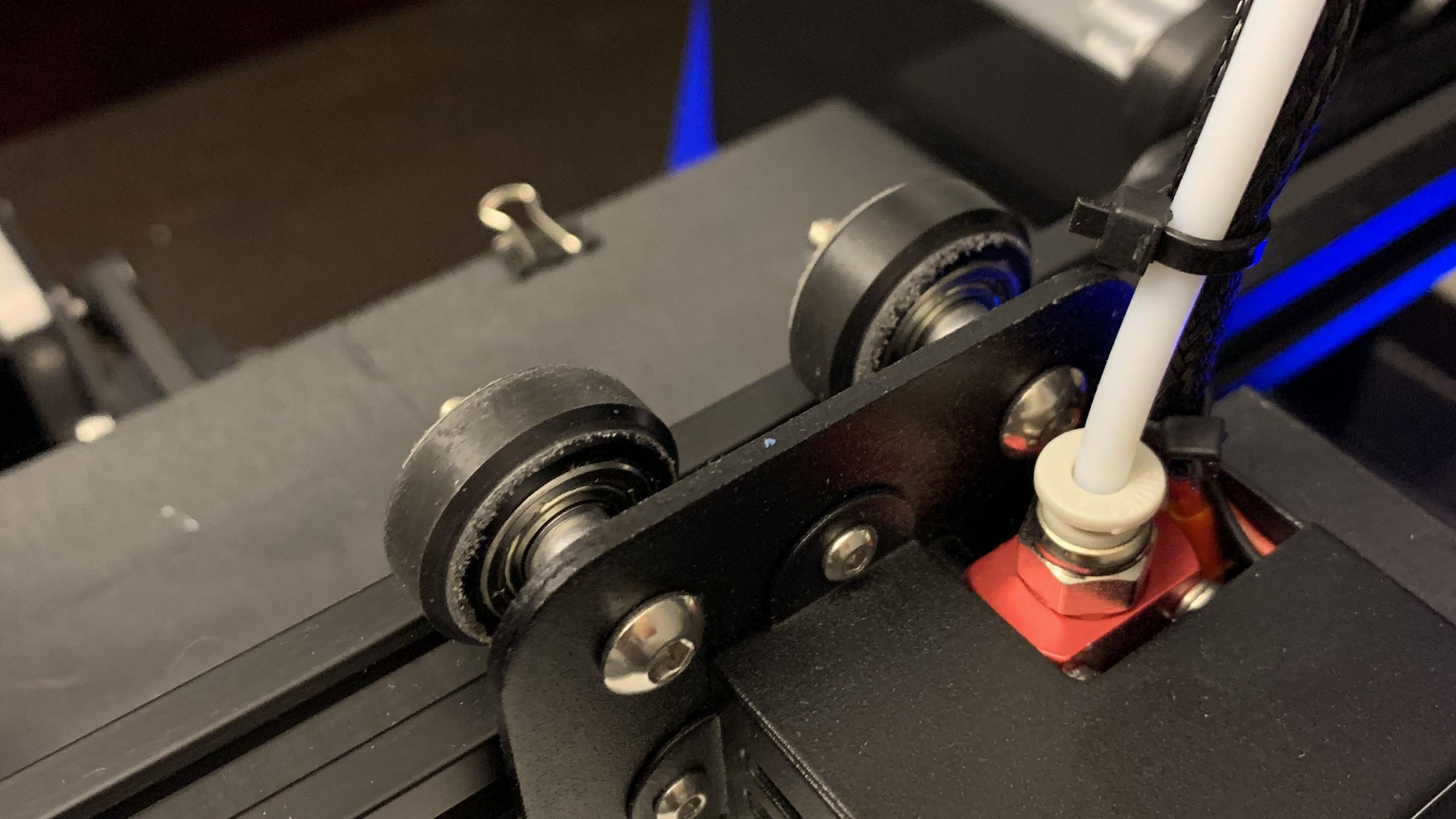
If you over tighten, it forces the motor controlling it to work harder and reduce it's effective lifetime. It may also cause dimensional inaccuracies. Too loose will cause sloppy/uneven lines and poor dimensional tolerances.
Before completely tightening the two M4x16 screws, push down on the bracket between the screws. This helps to ensure that the x-axis is at a proper right angle to the wheels while tightening each screw. If you run your finger along the edge of the bracket parallel to the extrusion it should feel even the entire length.
Step 8
When tightening the belt, apply pressure on the side of the bracket closest to the screws. After tightening the screws, ensure that they've rotated 90°. The belt should feel like a guitar string when you pluck it with your finger, vibrating for a quick moment before stopping.
Step 9
Before sliding on the x-axis gantry, lightly loosen the bolts for each upright. Slide the gantry onto both sides, then tighten the eccentric nut on each bracket following the same guidelines in step 7 for tightening the wheels. Make sure to slightly loosen the screws for the z-screw nut, highlighted in red in the instruction manual. Once you've mounted the gantry and checked that the wheels on each bracket are set properly, completely tighten down the screws for the upright.
Step 10
Lay the top extrusion (19) across the top of the two uprights. It should lay flat against each side. Screw in one side, but don't completely tighten it yet. Check that this sits at a right angle to the upgright. Do the same for the other side. If it doesn't lay flat or there is resistance in the bolts, STOP. Go back through the frame and make sure everything is square. If not, it will skew prints and greatly affect print dimensions. Once it's all set properly, tighten the bolts.
Step 11
No Additional Notes For This Step.
Step 12
The x-axis limit switch is inside the plastic cover with the QR code on it on the left side of the machine. Turn the connector so that the flat side faces toward the front of the machine, and use the screwdriver included in the tool kit to gently push it into place until you feel it click.
Software
Stock software included with the Creality printer SD memory card. You may find more up-to-date software at Ultimaker Cura
Support Guide
These are links to the official Creality Support troubleshooting & support guides
- Ender-3 Pro User Manual
- Maintenance flow chart (image)
- Troubleshooting (pdf)
- CHEP_Ender_3_bed_level.gcode (4-point calibration code)
Test Files
These are the included Creality test files, configured for PLA filament printing
Solarbotics, Ltd. is not responsible for misprints or errors on product prices or information. For more information, please see our Terms and Conditions.
Warning: This product contains chemicals known to the State of California to cause cancer and birth defects or other reproductive harm.
Please visit www.P65Warnings.ca.gov for more information. This item was manufactured prior to August 31, 2018.