Every once in a while we like to re-arrange the furniture. Sure, it's nice to have things look new and different, but most of the time we're just trying to make things just work better. This week we've done a little bit of restructuring of our Advanced category - we hope it'll make it easier […]
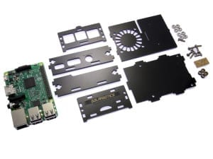
Solarbotics Raspberry Pi 3 SAFE Assembly...
The instructions for assembling the Pi v3 and the previous acrylic Pi SAFE are quite similar. The only difference between the models is the location of the LED light pipes, so these Pi3 instructions apply generally to all Pi SAFE versions.
1. Your Parts!

- 8 x 4-40 nuts
- 8 x 4-40 x 3/8" bolts
- 2 x Clear acrylic light-pipes
- 4 x Black acrylic spacers
- 6 x Black acrylic SAFE sides (shown here with brown protective paper already removed)
- 0 x Raspberry Pi (sorry - not included in the kit!)
2. The Baseplate
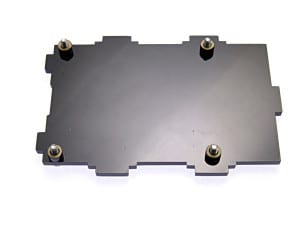
Find 4 of the 4-40 x 3/8" bolts, and put them through the baseplate, and press the spacers on from the other side. Thee bolts will sort of stay put until you can get the Raspberry Pi on the baseplate. (If adding to a VESA mount, do only 2 diagonal screws)
3. Adding the Raspberry Pi
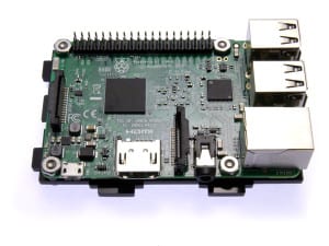
Slide the Raspberry Pi onto the bolts. The Pi is designed for metric M3 hardware, but we're still using imperial #4 hardware, which is a smidge bigger. The bolts may need to be screwed through the holes in the Pi.
Add the #4 nuts, and tighten them down.
4. Adding 3 of the 4 Sides
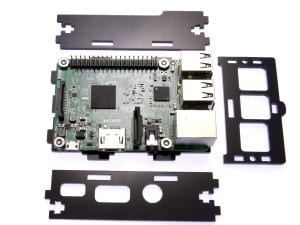
Arrange the sides as shows. The sideplate on the top in this image has the long cutout to accommodate a ribbon cable from the 40-pin expansion port. The front faceplate on the right (with the label engravings face-down) is for the communications side. The sideplate on the bottom has the ports for the power, video, and audio I/O.
Align them all up on the baseplate, and use a pair of 4-40 nuts and bolts to lock them in place.
5. Adding the SD-Card / LightPipe Faceplate
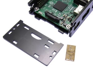
Lay the final side faceplate face-down beside the assembly, and pop the clear lightpipe parts out of their holder. It is not necessary to strip the paper off this part.
Sandwich the two lightpipes together, and push them into the lightpipe indicator hole. They will sit a bit loose until the faceplate is attached to the baseplate.
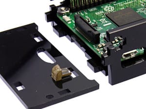
Carefully assemble this assembly to the baseplate, and finish attaching it with the remaining 4-40 nuts and bolts.
Step 6: Top Plate mounting
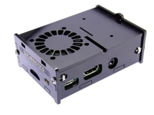
Notch the top plate into the slots in the rear faceplate, and gently flex the frontplate out to let the tab snap into place. You're ready to power up, with full access to the indication LEDs on the Pi mainboard via the lightpipes!
.
MORE POSTS
The SAFE (Solarbotics Arduino Freeduino Enclosure) is a marvelous contraption of laser-cut acrylic that makes a complete enclosure for your Arduino project. It gives you a protective shell with enough room for a basic shield, with knock-outs for power and USB connection. It even has a power switch. The big problem with Arduinos and Freeduinos, […]
It's cool. Well, not quite. But it's smoking. Umm, that's not right, either. It's anti-smoking. Whoever redesigned their 493 smoke absorber did a pretty good job - it's much better than it was before! And Hakko even posted a cool video showing how good it is (sorry, can't embed the video here).
Yes, we're Canadian, so we celebrate the Thanksgiving weekend a bit earlier than our neighbours to the South. Thus, we won't be in on Monday the 8th. But our website will always be here! Have a good Columbus Day down there!
Solarbotics, Ltd. is not responsible for misprints or errors on product prices or information. For more information, please see our Terms and Conditions.
Warning: This product contains chemicals known to the State of California to cause cancer and birth defects or other reproductive harm.
Please visit www.P65Warnings.ca.gov for more information. This item was manufactured prior to August 31, 2018.

