Although he has purchased from us, and used our products (the "Secret Motor Driver") in his prize-winning minisumo "Stinger", we, as Solarbotics officially declare Mr. Hylands only "marginal" friend. You see, Solarbotics sent a few of our robots to the University of Northern Idaho's mail-in minisumo contest, and again he's served our own tuckus back […]
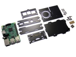
Solarbotics Raspberry Pi 3 SAFE Assembly...
The instructions for assembling the Pi v3 and the previous acrylic Pi SAFE are quite similar. The only difference between the models is the location of the LED light pipes, so these Pi3 instructions apply generally to all Pi SAFE versions.
1. Your Parts!

- 8 x 4-40 nuts
- 8 x 4-40 x 3/8" bolts
- 2 x Clear acrylic light-pipes
- 4 x Black acrylic spacers
- 6 x Black acrylic SAFE sides (shown here with brown protective paper already removed)
- 0 x Raspberry Pi (sorry - not included in the kit!)
2. The Baseplate
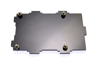
Find 4 of the 4-40 x 3/8" bolts, and put them through the baseplate, and press the spacers on from the other side. Thee bolts will sort of stay put until you can get the Raspberry Pi on the baseplate. (If adding to a VESA mount, do only 2 diagonal screws)
3. Adding the Raspberry Pi
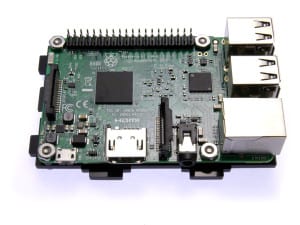
Slide the Raspberry Pi onto the bolts. The Pi is designed for metric M3 hardware, but we're still using imperial #4 hardware, which is a smidge bigger. The bolts may need to be screwed through the holes in the Pi.
Add the #4 nuts, and tighten them down.
4. Adding 3 of the 4 Sides
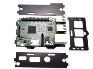
Arrange the sides as shows. The sideplate on the top in this image has the long cutout to accommodate a ribbon cable from the 40-pin expansion port. The front faceplate on the right (with the label engravings face-down) is for the communications side. The sideplate on the bottom has the ports for the power, video, and audio I/O.
Align them all up on the baseplate, and use a pair of 4-40 nuts and bolts to lock them in place.
5. Adding the SD-Card / LightPipe Faceplate
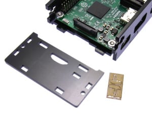
Lay the final side faceplate face-down beside the assembly, and pop the clear lightpipe parts out of their holder. It is not necessary to strip the paper off this part.
Sandwich the two lightpipes together, and push them into the lightpipe indicator hole. They will sit a bit loose until the faceplate is attached to the baseplate.
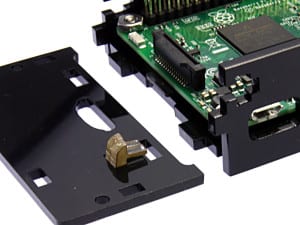
Carefully assemble this assembly to the baseplate, and finish attaching it with the remaining 4-40 nuts and bolts.
Step 6: Top Plate mounting
Notch the top plate into the slots in the rear faceplate, and gently flex the frontplate out to let the tab snap into place. You're ready to power up, with full access to the indication LEDs on the Pi mainboard via the lightpipes!
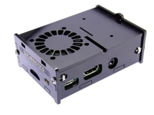
.
MORE POSTS
Yup, the Solarbotics.NET server we sponsor for the BEAM community is now online, offering more storage, RAM, speed, and open-source software to make your .net experience... better! (Well, we think so). No teething pains to report yet, although I'm sure we'll see some come up shortly. Stay tuned for more functionality as work continues...
So, didja all have a good Holiday Break? Yeah, we did too. Need a vacation to recover from the vacation... Enough chit-chat: Just a quick note to let you know we're expecting a bit of an outage January 6th at 2am MST (that's -7GMT, I think). Our server is being affected by an upstream upgrade […]
Well, we're disappointed. Not a single one of you fell for our Pimp Your Sumo April Fool's joke. Which is too bad, really, because we were actually ready to send them out to anyone that wanted one. Oh well, too late now! But don't fret if you missed out - we have a special treat […]
Solarbotics, Ltd. is not responsible for misprints or errors on product prices or information. For more information, please see our Terms and Conditions.
Warning: This product contains chemicals known to the State of California to cause cancer and birth defects or other reproductive harm.
Please visit www.P65Warnings.ca.gov for more information. This item was manufactured prior to August 31, 2018.

