Yes, it's true. After years of working our fingers to the bone inserting jumper wires on breadboards to make unusually robust controllers for robots out of discrete & logic chip elements, Solarbotics has seen the light! We've put on our eye-patch, hoisted the jolly-roger, and swung along-side to board the HMS HVWTech.com ! That's right […]
Arc Reactor Kit Assembly Instructions
Solar botics
April 26, 2016
Arc Reactor Kit Build Instructions
Here's a quick blog on how to assemble the Arc Reactor Kit - Limited Edition.
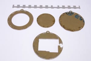
1. Remove brown paper from all 4 acrylic pieces - the pieces are actually clear, so remove all the paper from both sides.


2. Carefully push out the tiny plastic slivers using a small flat-headed screwdriver. The hardest is the thick piece, be careful with that one. They should all pop out with a bit of effort. They will push out from one side better than the other because of the kerf of the laser cutter.


3. Line up the ABS plastic strip with the switch slot.

4. Snip the 2 legs off of the pushbutton switch and solder remaining legs to pins 2 and 4 as shown:

5. Start pressing the ABS into the thick acrylic. Do it small amounts at a time: it is designed for a tight fit.


Cut and solder wires from the LED ring to the processor. Follow this table:
| Ring Pin | Processor Pin | Length | Color |
| PWR +5V | VCC | 5cm | Red |
| GND | GND | 5cm | Black |
| Data Input | 9 | 2cm | either |

5. Assemble Slide Switch / Battery connector - here's some points:
The switch has 3 pins - snip ONE end pin off. Only 2 pins are needed, the middle and one end.
For both the switch pins and the battery connector, be sure to use some heat shrink tubing to insulate the solder joints from each other. (In the photos, some of the heat shrink is yellow)
Always double check the polarity of the battery connector. The battery only plugs in one way, the black line is Gnd, and the red is +V.
|
Battery |
Slide Switch | LED Ring | Length | Color |
| RED | End Pin | n/a | 1cm | RED |
| n/a | Middle Pin | PWR +5V | 5cm | RED |
| BLACK | n/a | GND | 5cm | BLACK |


Be sure to heat the heat shrink once in place as it will shrink to 1/2 its diameter.


6. With everything soldered, it's time to start fitting the parts into the case. Start with the switch. From the front of the acrylic, (the side you inserted the PVC into) push the switch through the hole to the back side and slide it into the acrylic as shown.


Insert it into the acrylic, minding the pins. If you didn't trim the 1 side pin, now would be a good time to do so - it won't fit without trimming.
7. Attach the back plate to lock the switch in place.
8. Position the LED Ring on the front. Rotate it so that the processor fits within the bottom of the hole as shown.


9. Carefully insert the wires and battery connector into the space provided. There should be just enough room to squeeze the battery in as shown.

10. Once everything looks neat, place the small round disc in the middle of the LED ring and snap on the outer retention ring.


11. Snip a 5cm section of cord off to create a loop. Use a lighter or a torch to carefully melt the ends together.


12. Do the same with the rest of the cord to make a necklace.

MORE POSTS
Solarbotics at the ECRG
Well, somebody from Solarbotics will be at the Eastern Canadian Robot Games, namely Dave Hrynkiw, and Grant McKee. If you're going to be out in the Toronto region this weekend (October 26 and 27), come by and see the games at the Ontario Science Center!
Austin Maker Faire 2008
It's that wonderful time of year when you can see your breath in the air while you wait at the bus stop. Frost decorates the blades of grass, motorists spend five minutes scraping ice off the windshield before departing and there are hints of snow when you look up at the hills. So what's a […]
New Products: Frequency Generator, DIRRS...
Hello again everyone, this is Yana, the token Russian here at Solarbotics that brought you a newspost a little while ago. Here's a hypothetical question: what if you were asked to do a product post, again? As if one graceful and unexpected appearance two weeks ago was not enough for the audience to cherish those […]
Solarbotics has been operating for more than 25 years, bringing electronics know-how and supplies to both the electronics professional and hobbyist. We'll be happy to help you too!
Solarbotics, Ltd. is not responsible for misprints or errors on product prices or information. For more information, please see our Terms and Conditions.
Warning: This product contains chemicals known to the State of California to cause cancer and birth defects or other reproductive harm.
Please visit www.P65Warnings.ca.gov for more information. This item was manufactured prior to August 31, 2018.