We're sorry to say that our GM11 is presently sold out. We've got more on the way, but it'll be about another month until they resurface. Sorry!
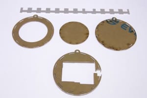
Arc Reactor Kit Assembly Instructions
Arc Reactor Kit Build Instructions
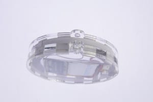
Here's a quick blog on how to assemble the Arc Reactor Kit - Limited Edition.
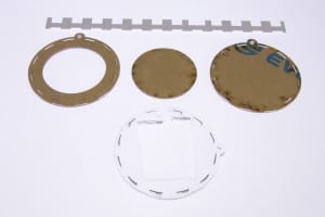
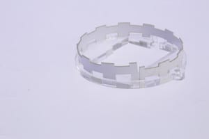
1. Remove brown paper from all 4 acrylic pieces - the pieces are actually clear, so remove all the paper from both sides.
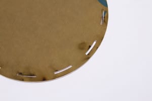
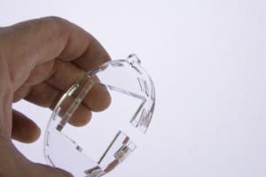
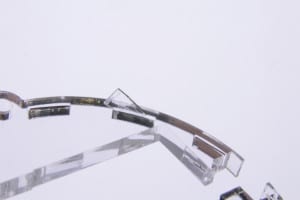
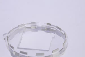
2. Carefully push out the tiny plastic slivers using a small flat-headed screwdriver. The hardest is the thick piece, be careful with that one. They should all pop out with a bit of effort. They will push out from one side better than the other because of the kerf of the laser cutter.
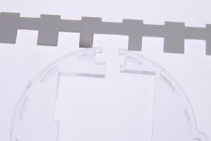
3. Line up the ABS plastic strip with the switch slot.
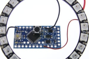
4. Snip the 2 legs off of the pushbutton switch and solder remaining legs to pins 2 and 4 as shown:
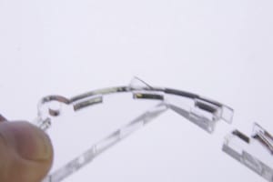
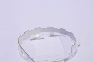
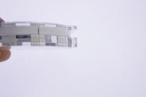
5. Start pressing the ABS into the thick acrylic. Do it small amounts at a time: it is designed for a tight fit.
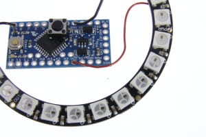
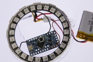
Cut and solder wires from the LED ring to the processor. Follow this table:
| Ring Pin | Processor Pin | Length | Color |
| PWR +5V | VCC | 5cm | Red |
| GND | GND | 5cm | Black |
| Data Input | 9 | 2cm | either |
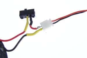
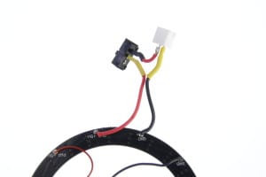
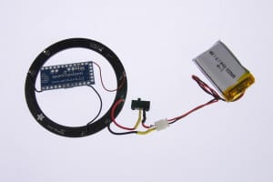
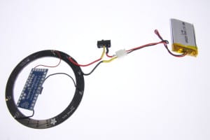
5. Assemble Slide Switch / Battery connector - here's some points:
The switch has 3 pins - snip ONE end pin off. Only 2 pins are needed, the middle and one end.
For both the switch pins and the battery connector, be sure to use some heat shrink tubing to insulate the solder joints from each other. (In the photos, some of the heat shrink is yellow)
Always double check the polarity of the battery connector. The battery only plugs in one way, the black line is Gnd, and the red is +V.
|
Battery |
Slide Switch | LED Ring | Length | Color |
| RED | End Pin | n/a | 1cm | RED |
| n/a | Middle Pin | PWR +5V | 5cm | RED |
| BLACK | n/a | GND | 5cm | BLACK |
Be sure to heat the heat shrink once in place as it will shrink to 1/2 its diameter.
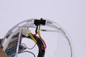
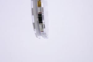
6. With everything soldered, it's time to start fitting the parts into the case. Start with the switch. From the front of the acrylic, (the side you inserted the PVC into) push the switch through the hole to the back side and slide it into the acrylic as shown.
Insert it into the acrylic, minding the pins. If you didn't trim the 1 side pin, now would be a good time to do so - it won't fit without trimming.
7. Attach the back plate to lock the switch in place.
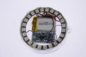
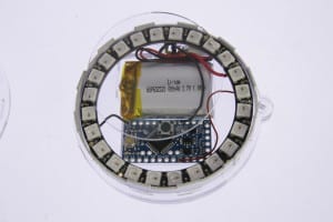
8. Position the LED Ring on the front. Rotate it so that the processor fits within the bottom of the hole as shown.
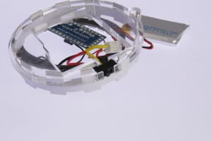
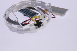
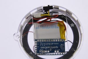
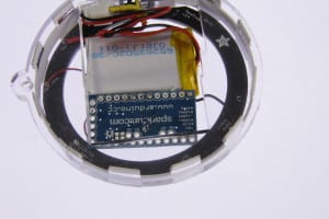
9. Carefully insert the wires and battery connector into the space provided. There should be just enough room to squeeze the battery in as shown.
10. Once everything looks neat, place the small round disc in the middle of the LED ring and snap on the outer retention ring.
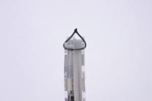
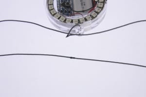
11. Snip a 5cm section of cord off to create a loop. Use a lighter or a torch to carefully melt the ends together.
12. Do the same with the rest of the cord to make a necklace.
MORE POSTS
Jeremie, our engineer and the brains behind the SB-FireFly, can't seem to put the thing down even though it's all done and released. He's been hard at work figuring out what it's capable of, and figures that the hardware and framework could be used for a Micro-TV-B-Gone broadcaster, IR code repeater, and even a tiny […]
We've had some requests on exactly what do the pushpins do. So, we added videos for two of them. Push Pin 1 (Masher Point) Push Pin 3 (Chisel Point)
We've tweaked the documentation for the BEP-MSE1 "Miller Solarengine" to correct a minor error (if you wanted to use the MVSE modification, this is the correct on), and added some circuit specs. Application notes for all the modules are in the works- stay tuned!
Solarbotics, Ltd. is not responsible for misprints or errors on product prices or information. For more information, please see our Terms and Conditions.
Warning: This product contains chemicals known to the State of California to cause cancer and birth defects or other reproductive harm.
Please visit www.P65Warnings.ca.gov for more information. This item was manufactured prior to August 31, 2018.

